As was the case with Experiment 4, this month’s experiment has been a big step forward, even if the music may not seem to indicate an advance. This is due to the fact that this is the first significant Organelle patch that I’ve created, and that I’ve figured out how to connect the EYESY to wifi, allowing me to transfer files to and from the unit. The patch I created, 2opFM, is based upon Node FM by m.wisniowski.
As the name of the patch suggests it is a two operator FM synthesizer. For those who are unfamiliar with FM synthesis, one of the two operators is a carrier, which is an audible oscillator. The other operator is an oscillator that modulates the carrier. In its simplest form, we can think of FM synthesis as being like vibrato. One oscillator makes sound, while the other oscillator changes the pitch of the carrier. We can think of two basic controls that affect the nature of the vibrato, the speed (frequency) of the modulating oscillator, and the depth of modulation, that is how far away from the fundamental frequency does the pitch move.
What makes FM synthesis different from basic vibrato is that typically the modulating oscillator is operating at a frequency within the audio range, often at a frequency that is higher in pitch than that of the carrier. Thus, when operating at such a high frequency, the modulator doesn’t change the pitch of the carrier. Rather it functions to shape the waveform of the carrier. FM Synthesis is most often accomplished using sine waves. Accordingly, as one applies modulation we start to add harmonics, yielding more complex timbres.
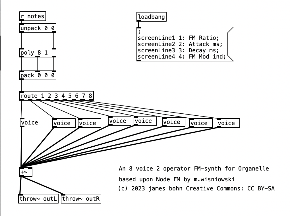
Going into detail about how FM synthesis shapes waveforms is well beyond the scope of this entry. However, it is worth noting that my application of FM synthesis here is very rudimentary. The four parameters controlled by the Organelle’s knobs are: transposition level, FM Ratio, release, and FM Mod index. Transposition is in semitones, allowing the user to transpose the instrument up to two octaves in either direction (up or down). FM Ratio only allows for integer values between 1 and 32. The fact that only integers are used here means that the result harmonic spectra will all conform to the harmonic series. Release refers to how long it will take a note to go from its operating volume to 0 after a note ends. The FM Mod index is how much modulation is applied to the carrier, with a higher index resulting in more harmonics added to a given waveform. I put this parameter on the leftmost knob, so that when I control the organelle via my wind controller, a WARBL, increases in air pressure will result in richer waveforms.
As can be seen in the screenshot of main.pd above, 2opFM is an eight voice synthesizer. Eight voice means that eight different notes can be played simultaneously when using a keyboard instrument. Each individual note is passed to the subroutine voice. Determining the frequency of the modulator involves three different parameters: the MIDI note number of the incoming pitch, the transposition level, and the FM ratio. We see the MIDI note number coming out of the left outlet of upack 0 0 on the right hand side, just below r notesIN-$0. For the carrier, we simply add this number to the transposition level, and then convert it to a frequency by using the object mtof, which stands for MIDI to frequency. This value is then, eventually passed to the carrier oscilator. For the modulator, we have to add the MIDI note number to the transposition level, convert it to a frequency, again using mtof, and multiplying this value by the FM Ratio.
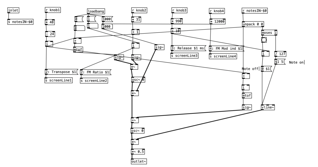
In order to understand the flow of this algorithm, we first have to understand the difference between control signals and audio signals. Audio signals are exactly what they sound like. In order to have high quality sound audio signals are calculated at the sample rate, which is 44,100 samples per section by default. In Pure Data, calculations that happen at this rate are indicated by a tilde following the object name. In order to save on processor time, calculations that don’t have to happen so quickly are control signals, which are denoted by a lack of a tilde after the object name. These calculations typically happen once every 64 samples, so approximately 689 times per second.
Knowing the difference between audio signals and control signals, we can now introduce two other objects. The object sig~ converts a control signal into an audio signal. Likewise, i converts a float (decimal value) to an integer, by truncating the value towards zero, that is positive values are rounded down, while negative values are rounded up.
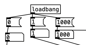
Keep in mind the loadbang portion of voice.pd is used to initialize the values. Here we see the transposition level set at zero, the FM ratio set to one, and the FM Mod index set to 1000. The values from the knobs come in as floats between 0 and 1 inclusive. Thus, typically in order to get useable values we have to perform mathematical operations to rescale them. Under knob 1, we see the transposition level multiplied by 48, and then we subtract 24 from that value. This will yield a value between -24 (two octaves down) and +24 (two octaves up). Under knob 2, we see the FM ratio multiplied by 31, and then we add one to this value, resulting in a value between 1 and 32 inclusive. Both of these values are converted to integers using i.
The scaled value of knob 1 (transposition level) is then added to the MIDI note number, and then turned into a frequency using mtof and converted to an audio signal using sig~. This is now the fundamental frequency of carrier oscillator. In order to get the frequency of the modulator, we need to multiply this value to the scaled value of knob 2. This frequency is then fed to the leftmost inlet of the modulating oscillator (osc~). The output of the modulating oscillator is then multiplied by the scaled output of knob 4 (0 to 12,000 inclusive), which is then in turn multiplied by the fundamental frequency of the carrier oscillator before being fed to the leftmost inlet of the carrier oscillator (osc~). While there is more going on in this subroutine, this explains how the core elements of FM synthesis are accomplished in this algorithm.
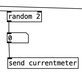
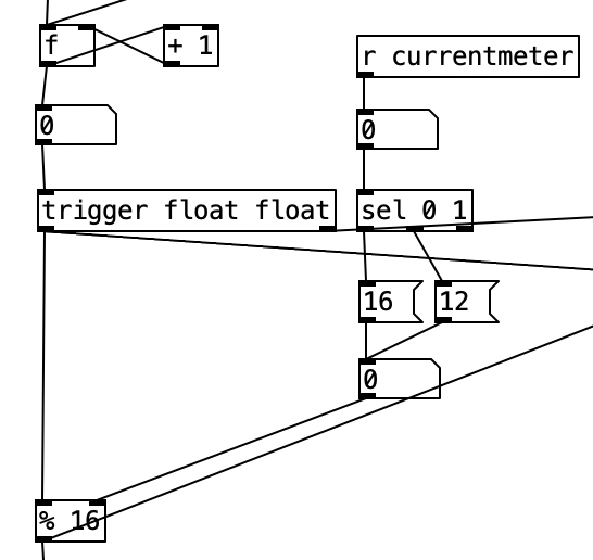
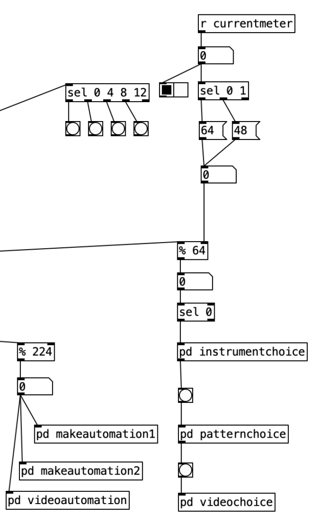
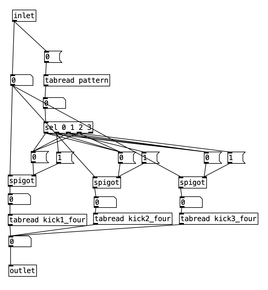
The algorithm that is used to generate the accompaniment is largely the same as the one used for Experiment 4 with a couple of changes. First, after completing Experiment 4 I realized I had to find a way to set the sixteenth note counter to zero every time the meter is changed. Otherwise, occasionally when changing from one meter to another there may be one or two extra beats. However, reseting the counter to zero ruins the subroutine that sends automation values. Thus, I had to use two counters, one that keeps counting without being reset (on the right) and one that gets reset every time the meter changes (on the left).
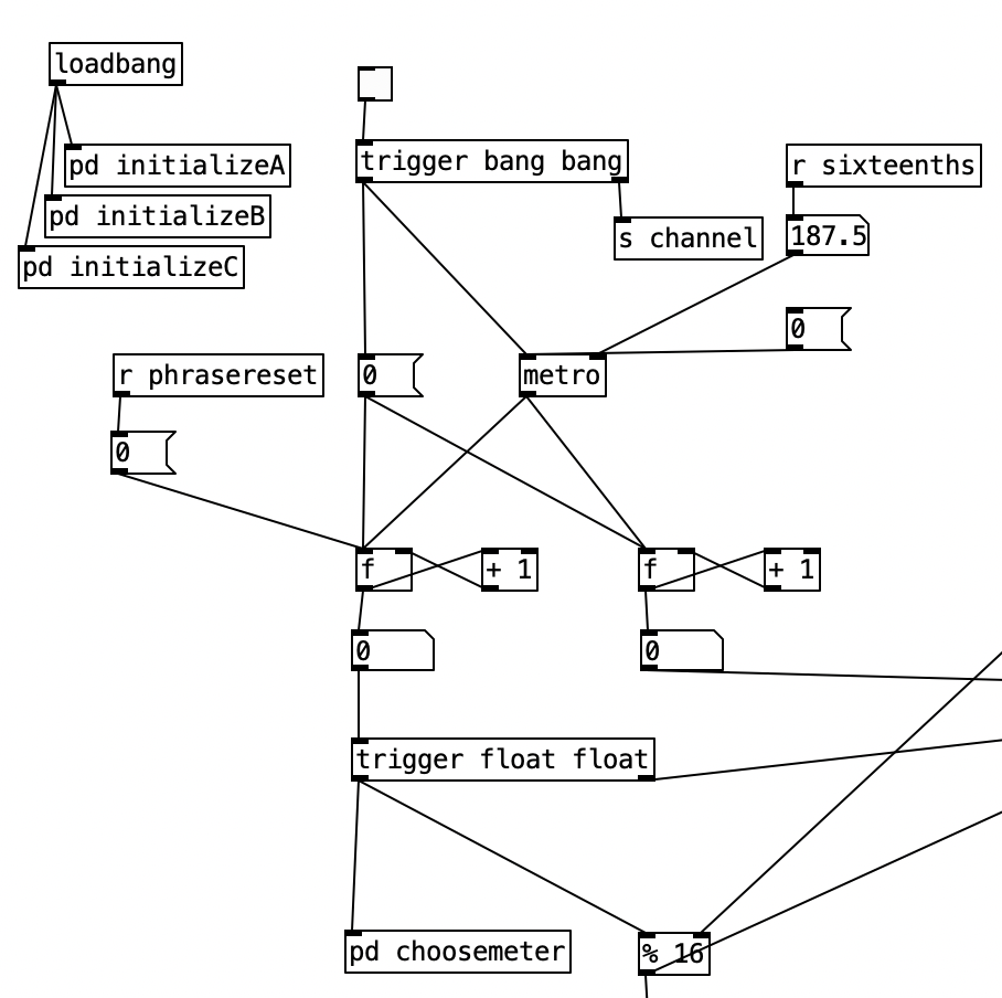
Initially I made a mistake by choosing the new meter at the beginning of a phrase. This caused a problem called a stack overflow. At the beginning of a phrase you’d chose a new meter, which would cause the phrase to reset, which would a new meter to be chosen, which then repeats in an endless loop. Thus, I had chose a new meter at the end of a phrase.
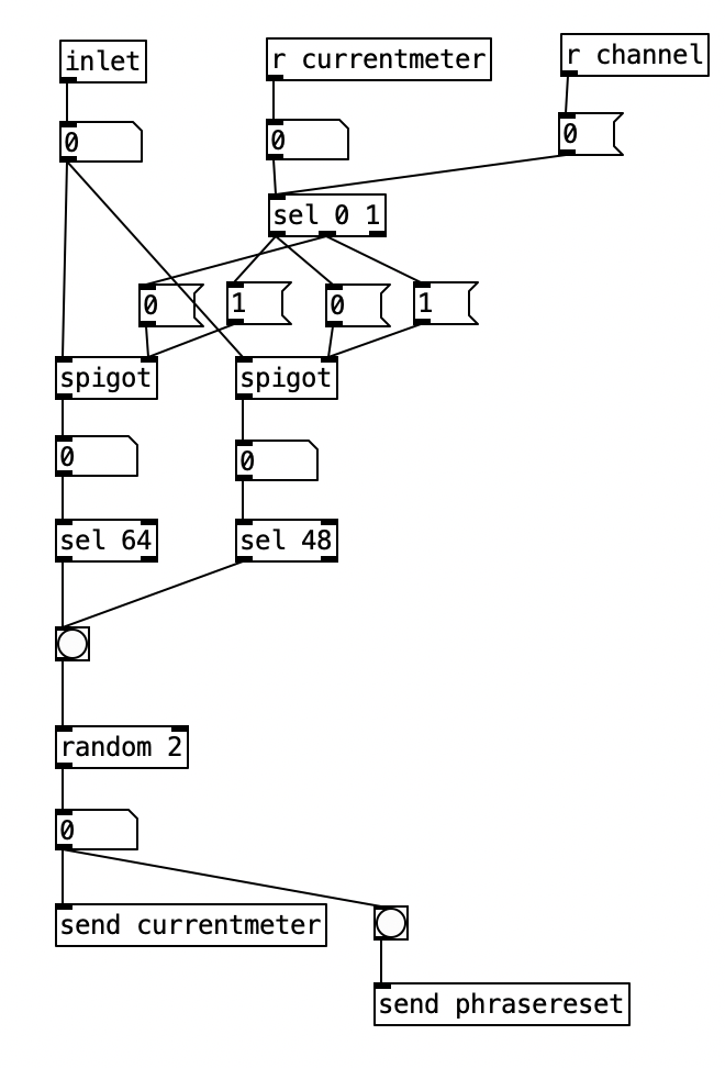
Inside pd choosemeter, we see the phrase counter being sent to two spigots. This spigots are turned on or off from depending on the value of currentmeter. The value 0 under r channel sets the meter for the first phrase to 4/4. Using the nomenclature of r channel is a bit confusing, as s channel is included in loadbang, and was simply included to initialize the MIDI channel numbers for the algorithm. In a future iteration of this program, I may retitle these values as s initializevalues and r initializevalues to make more sense.
Underneath the two spigots, we see sel 64 and sel 48, This finds the end of the phrase when we are in 4/4 (64) or 3/4 (48). Originally I had used the values 63 and 47 as these would be the numbers of the last sixteenth note of each phrase. However, when I did that I found that the algorithm skipped the last sixteenth note of the phrase. Thus, by using 64 and 48 I actually am choosing the meter at the start of a phrase, but now reseting the counter to zero no longer triggers a recursive loop. Regardless, whenever either sel statement is triggered the next meter is chosen randomly, with zero corresponding to 4/4 and 1 corresponding to 3/4. This value is then sent to other parts of the algorithm using send currentmeter, and the phrase is reset by sending a bang to send phrasereset.
As previously noted, I figured out how to connect the EYESY to wifi, allowing me to transfer files two and from the unit. Amongst other things, this allows me to download new EYESY programs from patchstorage.com and add them to my EYESY. I downloaded a patch called Image Shadow Grid, which was developed by dudethedev. This algorithm randomly grabs images stored inside a directory, adds them to the screen, and manipulates them in the process.
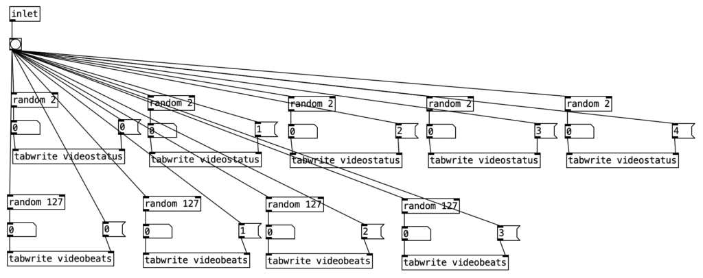
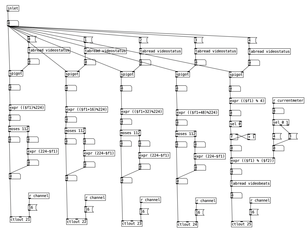
I was able to customize this program without changing any of the code simply by changing out the images in the directory. I added images related to a live performance of a piece from my forthcoming album (as Darth Presley). However, up to this point I’d been using the EYESY to respond mainly to audio volume. Some algorithms, such as Image Shadow Grid, use triggers to incite changes in the video output. The EYESY has several trigger modes. I chose to use the MIDI note trigger mode. However, in order to trigger the unit I now have to send MIDI notes to the EYESY.
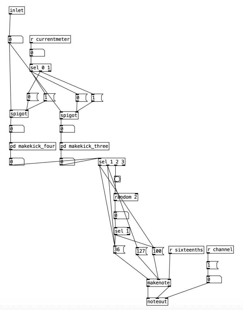
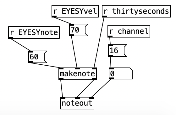
This constitute the other significant change to the algorithm that generates the accompaniment. I added a subroutine that sends notes to the EYESY. Since the pitch of the notes don’t matter, I simply send the number for middle C (60) to the unit. Otherwise the subroutine which determines whether a note should be sent to the EYESY functions just like those used to generate any rhythm, that is it selects between one of three rhythmic patterns for each of the two meters, each pattern of which is stored as an array.
As with last month, the significant weakness in this month’s experiment is my lack of practice on the WARBL. Likewise, it would have been useful if I had the opportunity to add a third meter to the algorithm that generates the accompaniment. The Organelle program 2opFM is not quite as expressive with the WARBL as it had been in experiment 2 and 4. Changes in the FM Mod Index aren’t as smooth as I had hoped they’d be. Perhaps if I were to expand the patch further, I’d want to add a third operator, and separate the FM Mod Index into two parts, one where you set the maximum level of the index, and another where you set the current level, so you can set it where the maximum breath pressure on the WARBL only yields a subtle amount of modulation.
In terms of the EYESY, I doubt I will begin writing programs for it next month, I may experiment with already existing algorithms that allow the EYESY to use a webcam. However, hopefully by October I can be hacking some Python code for the EYESY. My current plan is to experiment with some additive synthesis next month, so stay tuned.

