Experiment 9: Wavetable Sampler

This month’s experiment is a considerable step forward on three fronts: Organelle programming, EYESY programming, and computer assisted composition. In terms of Organelle programming, rather than taking a pre-existing algorithm and altering it (or hacking it) to do something different, I decided to create a patch from scratch. I first created it in PureData, and then reprogrammed it to work specifically with the Organelle. Creating it in PureData first meant that I used horizontal sliders to represent the knobs, and that I sent the output to the DAC (digital to analog converter). When coding for the Organelle, you use a throw~ object to output the audio.

The patch I wrote, Wavetable Sampler, reimagines a digital sampler, and in doing so, basically reinvents wavetable synthesis. The conventional approach to sampling is to travel through the sound in a linear fashion from beginning to end. The speed at which we travel through the sound determines both its length and its pitch, that is faster translates to shorter and higher pitched, while slower means longer and lower pitched.

I wanted to try using an LFO (low frequency oscillator) to control where we are in a given sample. Using this technique the sound would go back and forth between two points in the sample continuously. In my programming I quickly learned that two parameters are strongly linked, namely the frequency of this oscillator and the amplitude of the oscillator, which becomes the distance travelled in the sample. If you want the sample to be played at a normal speed, that is we recognize the original sample, those two values need to be proportional. To describe this simply, a low frequency would require the sample to travel farther while a higher frequency would need a small amount of space. Thus, we see the object expr (44100 / ($f1)), with the number 44,100 being the sample rate of the Organelle. Dividing the sample rate by the frequency of the oscillator yields the number of samples that make up a cycle of sound at that frequency.

Obviously, a user might want to specifically move at a different rate than what would be normal. However, making that a separate control prevents the user from having to mentally calculate what would be an appropriate sample increment to have the sample play back at normal speed. I also specified that a user will want to control where we are in a much longer sample. For instance, the sample I am using with this instrument is quite long. It is an electronic cello improvisation I did recently that lasts over four minutes.

The sound I got out of this instrument was largely what I expected. However, there was one aspect that stood out more than I thought it would. I am using a sine wave oscillator in the patch. This means that the sound travels quickly during the rise and fall portion of the waveform, but as it approaches the peak and trough of the waveform it slows down quite dramatically. At low frequencies this results in extreme pitch changes. I could easily have solved this issue by switching to a triangle waveform, as speed would be constant using such a waveform. However, I decided that the oddness of these pitch changes were the feature of the patch, and not the bug.

While I intended the instrument to be used at low frequencies, I found that it was actually far more practical and conventionally useful at audio frequencies. Human hearing starts around 20Hz, which means if you were able to clap your hands 20 times in a second you would begin to hear it as a very low pitch rather than a series of individual claps. One peculiarity of sound synthesis is that if you repeat a series of samples, no mater how random they may be, at a frequency that lies within human hearing, you will hear it as a pitch that has that frequency. The timbre between two different sets of samples at the same frequency may vary greatly, but we will hear them as being, more or less, the same pitch.

Thus, as we move the frequency of the oscillator up into the audio range, it turns into somewhat of a wavetable synthesizer. While wavetable synthesis was created in 1958, it didn’t really exist in its full form until 1979. At this point in the history of synthesis it was an alternative to FM synthesis, which could offer robust sound possibilities but was very difficult to program, and digital sampling, which could recreate any sound that could be recorded but was extremely expensive due to the cost of memory. In this sense wavetable synthesis is a data saving tool. If you imagine a ten second recording of a piano key being struck and held, the timbre of that sound changes dramatically over those ten seconds, but ten seconds of sampling time in 1980 was very expensive. Imagine if instead we can digitize individual waveforms at five different locations in the ten second sample, we can then gradually interpolate between those five waveforms to create a believable (in 1980) approximation of the original sample. That being said, wavetable synthesis also created a rich, interesting approach to synthesizing new sounds such that the technique is still somewhat commonly used today.

When we move the oscillator for Wavetable Sampler into the audio range, we are essentially creating a wavetable. The parameter that effects how far the oscillator travels through the sample creates a very interesting phenomenon at audio rates. When that value is very low, the sample values vary very little. This results in waveforms that approach a sine wave in their simplicity and spectrum. As this value increases more values are included, which may differ greatly from each other. This translates into adding harmonics into the spectrum. Which harmonics are added are dependent up the wavetable, or snippet of a sample, in question. However, as we turn up the value, it tends to add harmonics from lower ones to higher ones. At extreme values, in this case ten times a normal sample increment, the pitch of the fundamental frequency starts to be over taken by the predominant frequencies in that wavetable’s spectrum. One final element of interest with the construction of the instrument in relation to wavetable synthesis is related to the use of a sine wave for the oscillator. Since the rate of change speeds up during the rise and fall portion of the waveform and slows down near the peak and the valley of the wave, that means there are portions of the waveform that rich in change while other portions where the rate of change is slow.

Since the value that the oscillator travels seems to be analogous to increasing the harmonic spectrum, I decided to put that on knob four, as that is the knob I have been controlling via breath pressure with the WARBL. On the Organelle I set knob one to set the index of where we are in the four minute plus sample. The frequency of the oscillator is set by the key that is played, but I use the second knob as a multiplier of this value. This knob is scaled from .001, which will yield a true low frequency oscillator, to 1, which will be at the pitch played (.5 will be down an octave, .25 will be down two octaves, etc.). As stated earlier, the fourth knob is used to modify the amplitude of the oscillator, affecting the range of samples that will be cycled through. This left the third knob unused, so I decided to use that as a decay setting.

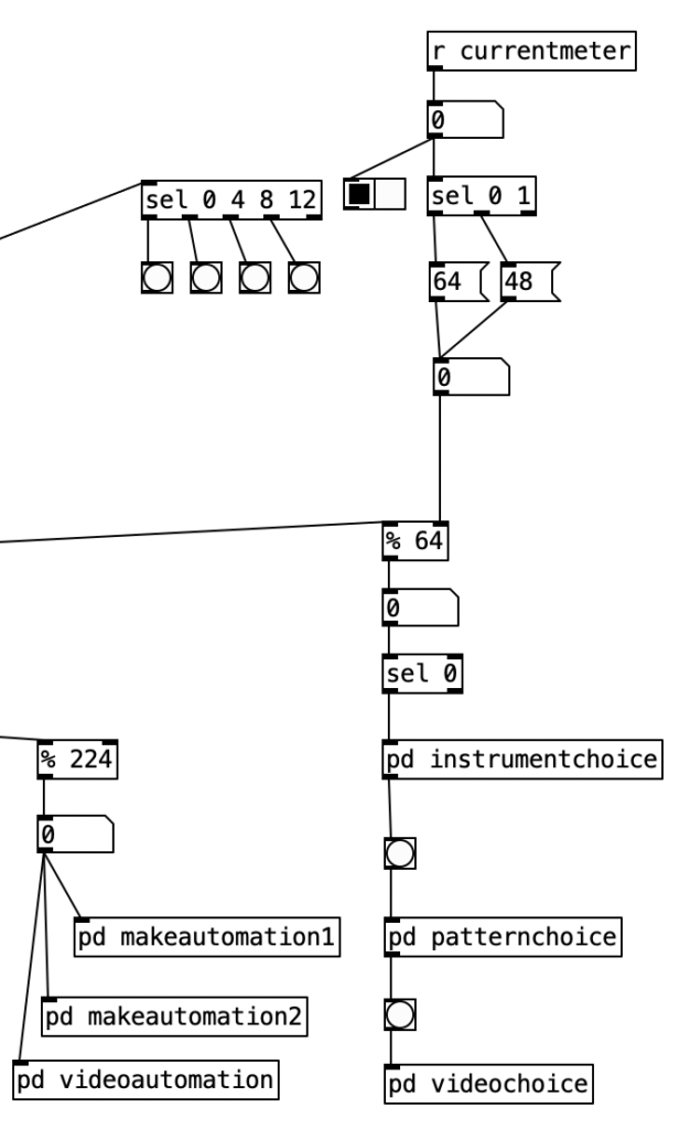
The PureData patch that was used to generate the accompaniment for this experiment was based upon the patch created for last month’s experiment. As a reminder, this algorithm randomly chooses between one of four musical meters, 4/4, 3/4, 7/8, and 5/8, at every new phrase. I altered this algorithm to fit a plan I have for six of the tracks on my next studio album, which will likely take three or four years to complete. Rather than randomly selecting them, I define an array of numbers that represent the meters that should be used in the order that they appear. At every phrase change I then move to the next value in the array, allowing the meters to change in a predetermined fashion.

I put the piece of magic that allows this to happen in pd phrasechange. The inlet to this subroutine goes to a sel statement that contains the numbers of new phrase numbers expressed in sixteenth notes. When those values are reached a counter is incremented, a value from the table meter is read, which is sent to the variable currentmeter and the phrase is reset. This subroutine has four outlets. The first starts a blinking light that indicates that the piece is 1/3 finished, the second outlet starts a blinking light that starts when the piece is 2/3 of the way finished. The third outlet starts a blinking light that indicates the piece is on its final phrase. The fourth outlet stops the algorithm, bringing a piece to a close. Those blinking lights are on the right hand side of the screen, located near the buttons that indicate the current meter and the current beat. A performer can then, with some practice watch the computer screen to see what the current meter is, what the current beat is, and to have an idea of where you are in form of the piece.

This month I created my first program for the EYESY, Basic Circles. The EYESY manual includes a very simple example of a program. However, it is too simple it just displays a circle. The circle doesn’t move, none of the knobs change anything, and the circle isn’t even centered. With very little work I was able to center the circle, and change it so that the size of the circle was controlled by the volume of the audio. Likewise, I was able to get knob four to control the color of the circle, and the fifth knob to control the background color.

However, I wanted to create a program that used all five knobs on the EYESY. I quickly came up with the idea of using knob two to control the horizontal positioning, and the third knob to control the vertical positioning. I still had one knob left, and only a simple circle in the middle of the screen to show for it. I decided to add a second circle, that was half the size of the first one. I used knob five to set the color for this second circle, although oddly it does not result in the same color as the background. Yet, this still was not quite visually satisfying, so I set knob one to set an offset from the larger circle. Accordingly, when knob one is in the center, the small circle is centered within the larger one. As you turn the knob to the left the small circle moves to the upper left quadrant of the screen. As you turn the knob to the right the smaller circle moves towards the lower right quadrant. This is simple, but offers just enough visual interest to be tolerable.

import os
import pygame
import time
import random
import math

def setup(screen, etc):
    pass

def draw(screen, etc):
	size = (int (abs (etc.audio_in[0])/100))
	size2 = (int (size/2))
	position = (640, 360)
	color = etc.color_picker(etc.knob4)
	color2 = etc.color_picker(etc.knob5)
	X=(int (320+(640*etc.knob2)))
	X2=(int (X+160-(310*etc.knob1)))
	Y=(int (180+(360*etc.knob3)))
	Y2=(int (Y+90-(180*etc.knob1)))
	etc.color_picker_bg(etc.knob5)  
	pygame.draw.circle(screen, color, (X,Y), size, 0)
	pygame.draw.circle(screen, color2, (X2,Y2), size2, 0)

While the program, listed above, is very simple, it was my first time programming in Python. Furthermore, targeting the EYESY is not the simplest thing to do. You have plug a wireless USB adapter into the EYESY, connect to the EYESY via a web browser, upload your program as a zip file, unzip the file, and then delete the zip file. You then have to restart the video on the EYESY to see if the patch works. If there is an error in your code, the program won’t load, which means you cannot trouble shoot it, you just have to look through your code line by line and figure it out. Although, I learned to use an online Python compiler to check for basic errors. If you have a minor error in your code the EYESY will sometimes load the program and display a simple error message onscreen, which will allow you to at least figure where the error is.

I’m very pleased with the backing track, and given that it is my first program for the EYESY, with the visuals. I’m not super pleased with the audio from the Organelle. Some of this is due to my playing. For this experiment I used a very limited set of pitches in my improvisation, which made the fingering easier than it has been in other experiments. Also, I printed out a fingering chart and kept it in view as I played. Part of it is due to my lack of rhythmic accuracy. I am still getting used to watching the screen in PureData to see what meter I am in and what the current beat is. I’m sure I’ll get the hang of it with some practice.

One fair question to ask is do I continue to use the WARBL to control the Organelle if I consistently find it so challenging? The simple answer is that consider a wind controller to be the true test of the expressiveness of a digital musical instrument. I should be able to make minute changes to the sound by slight changes in breath pressure. After working with the Organelle for nine months, I can say that it fails this test. The knobs on the Organelle seem to quantize at a low resolution. As you turn a knob you are changing the resistance in a circuit. The resulting current is then quantized, that is its absolute value is rounded to the nearest digital value. I have a feeling that the knobs on the Organelle quantize to seven bits in order to directly correspond to MIDI, which is largely a seven bit protocol. Seven bits of data only allow for 128 possible values. Thus, we hear discrete changes rather than continual ones as we rotate a knob. For some reason I find this short coming is amplified rather than softened when you control the Organelle with a wind controller. At some point I should do a comparison where I control a PureData patch on my laptop using the WARBL without using the Organelle.

I recorded this experiment using multichannel recording, and I discovered something else that is disappointing about the Organelle. I found that there was enough background noise coming from the Organelle that I had to use a noise gate to clean up the audio a bit. In fact, I had to set the threshold at around -35 dB to get rid of the noise. This is actually pretty loud. The Volca Keys also requires a noise gate, but a lower threshold of -50 or -45 dB usually does the trick with it.

Perhaps this noise is due to a slight ground loop, a small short in the cable, RF interference, or some other problem that does not originate in the Organelle, but it doesn’t bode well. Next month I may try another FM or additive instrument. I do certainly have a good head start on the EYESY patch for next month.

Experiment 8: Bass Harmonica

For this month’s experiment I created a sample player that triggers bass harmonica samples. I based the patch off of Lo-Fi Sitar by a user called woiperdinger. This patch was, in turn, based off of Lo-Fi Piano by Henr!k. According to this user, this was based upon a patch called Piano48 by Critter and Guitari.

The number 48 in the title refers to the number of keys / samples in the patch. Accordingly, my patch has the potential for 48 different notes, although only 24 notes are actually implemented. This is due to the fact that the bass harmonica I used to create the sample set only features 24 pitches. I recorded the samples using a pencil condenser microphone. I pitch corrected each note (my bass harmonica is fairly out of tune at this point), and I EQed each note to balance the volumes a bit. Initially I had problems as I had recorded the samples at a higher sample rate (48kHz) than the Organelle operates at (44.1kHz). This resulted in the pitch being higher than planned, but it was easily fixed by adjusting the sample rate on each sample. I had planned on recording the remaining notes using my Hohner Chromonica 64, but I ran out of steam. Perhaps I will expand the sample set in a future release.

The way this patch works is that every single note has its own sample. Furthermore, each note is treated as its own voice, such that my 24 note bass harmonica patch allows all 24 notes to be played simultaneously. The advantage of having each note have its own sample is that each note will sound different, allowing the instrument to sound more naturalistic. For instance the low D# in my sample set is really buzzy sounding, because that note buzzes on my instrument. Occasionally hitting a note with a different tone color makes it sound more realistic. Furthermore, none of the samples have to be rescaled to create other pitches. Rescaling a sample either stretches the time out (for a lower pitch) or squashes the time (for a higher pitch), again creating a lack of realism.

The image above looks like 48 individual subroutines, but it is actually 48 instantiations of a single abstraction. The abstraction is called sampler-voice, and each instance of this abstraction is passed the file name of the sample along with the key number that triggers the sample. The key numbers are MIDI key numbers, where 60 is middle C, and each number up or down is one chromatic note away (so 61 would be C#).

Inside sampler-voice we see basically two algorithms, one that executes when the abstraction loads (using loadbang), and one that runs while the algorithm is operating. If we look at the loadbang portion of the abstraction, we see that it uses the object soundfiler to load the given sample into an array. This sample is then displayed in the canvas to the left. Soundfiler sends the number of samples to its left outlet. This number is then divided by 44.1 to yield the time in milliseconds.

As previously stated, the balance of the algorithm operates while the program is running. The top part of the algorithm, r notes, r notes_seq, r zero_notes, listens for notes. The object stripnote is being used to isolated the MIDI note number of the given event. This is then passed through a mod (%) 48 object as the instrument itself only has 48 notes. I could have changed this value to 24 if I wanted every sample to recur once every two octaves. The object sel $2 is then use to filter out all notes except the one that should trigger the given sample ($2 means the second value passed to the abstraction). The portion of the algorithm that reads the sample from the array is tabread4~ $1-array.

Knob 1 of the Organelle is used to control the pitch of the instrument (in case you want to transpose the sample). The second knob is used to control both the output level of the reverb as well as the mix between the dry (unprocessed) sound and the wet (reverberated) sound. In Lo-Fi Sitar, these two parameters each had their own knob. I combined them to allow for one additional control. Knob 3 is a decay control that can be used if you don’t want the whole sample to play. The final knob is used to control volume, which is useful when using a wind controller, such as the Warbl, as that can be used to allow the breath control to control the volume of the sample.

The PureData patch that controls the accompaniment is basically the finished version of the patch I’ve been expanding through this grant project. In addition to the previously used meters 4/4, 3/4, and 7/8, I’ve added 5/8. I’d share information about the algorithm itself, but it is just more of the same. Likewise, I haven’t done anything new with the EYESY. I’m hoping next month I’ll have the time to tweak an existing program for EYESY, but I just didn’t have the time to do that this month.
I should have probably kept the algorithm at a slower tempo, as I think the music works better at a slower tempo. The bass harmonica samples sound fairly natural, except for when the Organelle seems to accidentally trigger multiple samples at once. I have a theory that the Warbl uses a MIDI On message with a velocity of 0 to stop notes, which is an acceptable use of a MIDI On message, but that PureData uses it to trigger a note. If this is the case, I should be able to fix it in the next release of the patch.

It certainly sounds like I need to practice my EVI fingering more, but I found the limited pitch range (two octaves) of the sample player made the fingering easier to keep track of. Since you cannot use your embouchure with an EVI, you use range fingerings in order to change range. With the Warbl, your right hand (lower hand) is doing traditional valve fingerings, while your left hand (upper hand) is doing fingerings based upon traditional valve fingerings to control what range you are playing on. Keeping track of how the left hand affects the notes being triggered by the right hand has been my stumbling block in terms of learning EVI fingering. However, a two octave range means you really only need to keep track of four ranges. I found the breath control of the bass harmonica samples to be adequate. I think I’d really have to spend some time calibrating the Warbl and the Organelle to come up with settings that will optimize the use of breath control. Next month I hope to create a more fanciful sample based instrument, and maybe move forward on programming for the EYESY.

Experiment 7: Additive Odd / Even

I’m afraid I’m not as pleased with this month’s entry as I had hoped to be. The instrument I developed worked fairly well on the Organelle, but when I used it in combination with a wind controller, it was not nearly as expressive as I had hoped. I had also hoped to use the EYESY with a webcam, but I was not able to get the EYESY to recognize either of my two USB webcams. That being said, I think the instrument I designed is a good starting point for further development.

The instrument I designed, Additive Odd Even, is an eight-voice additive synthesizer. Additive synthesis, as the name implies, is an alternative approach to subtractive synthesis. Subtractive synthesis was the most common approach for the first decades of synthesis, as it requires the fewest / least expensive components in comparison to most other approaches. Subtractive synthesis involves taking periodic waveforms that have rich harmonic content, and using filters to subtract some of that content to create new sounds.

Additive synthesis was theorized by rarely attempted since the beginning of sound synthesis. Technically speaking the early behemoth, the Teleharmonium, used additive synthesis. Likewise, earlier electronic organs often used some variant of additive synthesis. One of the few true early additive synthesizers was the Harmonic Tone Generator. However, this instrument’s creator, James Beauchamp only made two of them.

Regardless, additive synthesis involves adding pure sine tones together to create more complex waveforms. In typical early synthesizers, this was impractical, as it would require numerous expensive oscillators in order to accomplish this approach. As a point of reference, the Harmonic Tone Generator only used six partials.

Additive Odd Even is based upon Polyphonic Additive Synth by user wet-noodle. In my patch, knob one controls the transposition level, allowing the user to raise or lower the pitch chromatically up to two octaves in either direction. The second knob controls the balance of odd versus even partials. When this knob is in the middle, the user will get a sawtooth wave, and when it is turned all the way to the left, a square wave will result. Knob three controls both the attack and release, which are defined in terms of milliseconds, ranging from 0 to 5 seconds. The final knob controls the amount of additive synthesis applied, yielding a multiplication value of 0 to 1. This last knob is the one that is controlled by the amount of breath pressure from the WARBL. Thus, in theory, as more breath pressure is supplied, we should hear more overtones.

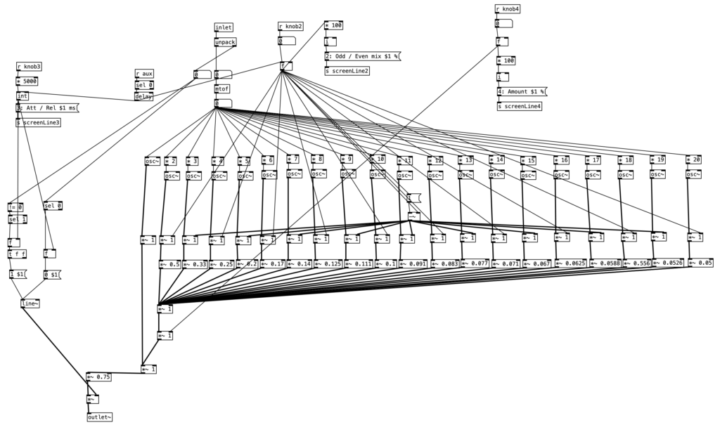
This instrument consists only of a main routine (main.pd) and one abstraction (voice.pd). Knob one is controlled in the main routine, while the rest exist in the abstraction. As we can see below, voice.pd contains 20 oscillators, which in turn provide 20 harmonic partials for the sound. We can see this in the way in which the frequency of each successive oscillator is multiplied by integers 1 through 20. A bit below these oscillators, we see that the amplitudes of these oscillators is multiplied by successively smaller values from 1 down to .05. These values roughly correspond to 1/n, where n is the harmonic value. Summing these values together would result in a sawtooth waveform.

We see more multiplication / scaling above these values. Half of them come directly from knob 2, which controls the odd / even mix. These are used to scale only the even numbered partials. Thus, when the second knob is turned all the way to the left, the result is 0, which effectively turns off all the even partials. This results in only the odd partials being passed through, yielding a square waveform. The odd numbered partials are scaled using 1 minus the value from the second knob. Accordingly, when knob 2 is placed in the center position, the balance between the odd and even partials should be the same, yielding a sawtooth wave. Once all but the fundamental is scaled by knobs 2 & 4, they are mixed together, and mixed with the fundamental. Thus, we can see that neither knob 2 nor 4 affects the amplitude of thefundamental partial. This waveform is then scaled by .75 to avoid distortion, and then scaled by the envelope, provided by knob three.

In August I had about one month of data loss. Accordingly, I lost much of the work I did on the PureData file that I used to generate the accompaniment for Experiment 5. Fortunately I had the blog entry for that experiment to help me reconstruct that program. I also added a third meter, 7/8, in addition to the two meters used in Experiment 5 (4/4 and 3/4). Most of the work to add this is adding a bunch of arrays, and continuing the expansion of the algorithm that was already covered in the blog entry for Experiment 5.

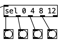
That being said, using an asymmetrical meter such as 7/8 creates a challenge for the visual metronome I added in experiment 5. Previously I was able to put a select statement, sel 0 4 8 12 that comes from the counter that tracks the sixteenth notes in a given meter. I could then connect each of the four leftmost outlets of that sel statement to a bang. Thus, each bang would activate in turn when you reach a downbeat (once every 4 sixteenth notes).

However, asymmetrical meters will not allow this to work. As the name suggests, in such meters the beat length is inconsistent. That is there are beats that are longer, and ones that are shorter. The most typical way to count 7/8 is to group the eighth notes with a group of 3 at the beginning, and to have two groups of 2 eighths at the end of the measure. This results in a long first beat (of 3 eighths or 6 sixteenth notes), followed by two short beats (of 2 eighths or 4 sixteenth notes).

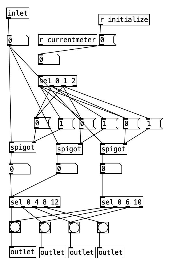
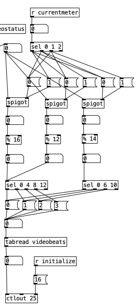
Accordingly, I created a new subroutine called pd count, which routes the sixteenth note count within the current measure based upon the current meter. Here we see that the value of currentmeter or a 0 sent by initialize is sent to a select statement that is used to turn on one of three spigots, and shut off the others. The stream is then sent to one of two select statements that identify when downbeats occur. Since both 4/4 an 3/4 use beats that are 4 sixteenth notes long, both of those meters can be sent to the same select statement. The other sel statement, sel 0 6 10, corresponds to 7/8. The second beat does not occur until the sixth sixteenth note, while the final downbeat occurs 4 sixteenth notes later at count 10.

One novel aspect of this subroutine is that it has multiple outlets. Each outlet is fed a bang. Each outlet of the subroutine is sent to a different bang, so the user can see the beats happen in real time. Note that this is next to a horizontal radio button, which displays the current meter. Thus, the user can use this to read both the meter, and which beat number is active.

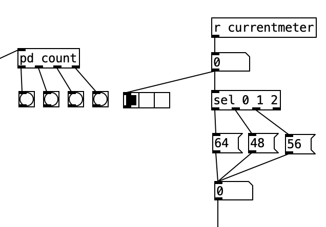
I had to essentially recreate the code inside pd count inside of pd videoautomation in order to change the value of knob 5 of the EYESY on each downbeat. Here the output from the select statements are sent to messages of 0 through 3, which correspond to beats 1 through 4. These values are then used as indexes to access values stored in the array videobeats.

I did not progress with my work on the EYESY during this experiment, as I had intended to use the EYESY in conjunction with a webcam, but unfortunately I could not get the EYESY to recognize either of my two USB webcams. I did learn that you can send MIDI program changes to the EYESY to select which scene or program to make use of. However, I did not incorporate that knowledge into my work.

One interesting aspect of the EYESY related to program changes is that it runs every program loaded onto the EYESY simultaneously. This allows seamless changes from one algorithm to another in real time. There is no need for a new program to be loaded. This operational aspect of the EYESY requires the programs be written as efficiently as possible, and Critter and Guitari recommends loading no more than 10MB of program files onto the EYESY at any given time so the operation does not slow down.

As stated earlier, I was disappointed in the lack of expression of the Additive Odd Even patch when controlled by the WARBL. Again, I need to practice my EVI fingering. I am not quite use to reading the current meter and beat information off of the PureData screen, but with some practice, I think I can handle it. While the programming changes for adding 7/8 to the program that generates the accompaniment is not much of a conceptual leap from the work I did for Experiment 5, it is a decent musical step forward.

Next month I hope to make a basic sample instrument for the Organelle. I will likely add another meter to the algorithm that generates accompaniment. While I’m not quite sure what I’ll do with the EYESY, I do hope to move forward with my work on it.

Experiment 6: Constant Gardener

It has been a busy month for me, so I’m afraid this experiment is not as challenging as it could be. I used the Organelle patch Constant Gardener to process sound from my lap steel guitar. This patch uses a phase vocoder, which allows the user to control speed and pitch of audio independently from each other. While I won’t go into great detail about what a phase vocoder is and how it works, it uses a fast Fourier transform algorithm to analyze an audio signal and to reinterpret it as time-frequency representation.

This process is dependent upon the Fourier analysis. The idea behind Fourier analysis is that complex functions can be represented as a sum of simpler functions. In audio this idea is used to separate complex audio signals into its constituent sine wave components. This idea is central to the concept of additive synthesis, which is based upon the idea that any sound, no matter how complex, can be represented by a number of sine wave elements that can be summed together. When we convert an audio signal to a time-frequency representation we get a three-dimensional analysis of the sound where one dimension is time, one dimension is frequency, and the third dimension is amplitude.

Not only can we use this data to resynthesize a sound, but in doing so, we can treat time and frequency separately. That is we can slow a sound down without making the pitch go lower. Likewise, we could raise the pitch of a sound without making the sound wave shorter.

Back to Constant Gardener. This patch uses knob 1 to control the speed (or time element) of the re-synthesis. Knob 2 controls the pitch of the resynthesis. The third knob controls the balance between the dry audio input to the Organelle with the processed (resynthesized) sound. The final knob controls how much reverb is added to the sound. The aux button (or foot pedal) is used to turn the phase vocoder resynthesis on or off.

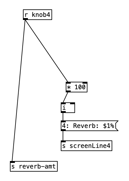
The phase vocoder part of the algorithm is sufficiently difficult such that I won’t attempt to go through it here, rather I will go through the reverb portion of the patch. As stated previously, knob four controls the balance between the dry (non-reverberated) and the reverberated sound. Thus value is then sent to the screen as a percentage, and is also sent to the variable reverb-amt using a number from 0 to 1 inclusive.

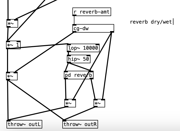
When the value of reverb-amt is recieved, it is sent to a subroutine called cg-dw. I’m not sure why the author of the patch used that name (perhaps cg stands for constant gardener), but this subroutine basically splits the signal in two, and modifies the value the will be returned out of the left outlet to be the inverse of the value of the right outlet (that is 1 – the reverb amount). Both values are passed through a low pass filter with cutoff frequency of 5 Hz, presumably to smooth out the signal.

The object lop~ 10000 receives its input from a chain that can be traced back to the input of the dry audio coming from the Organelle’s audio input. This object is a low pass filter, which means that the frequencies below the cutoff frequency, in this case 10,000 Hz, to pass through the filter, which in return attenuates the frequencies above the cutoff frequency. More specifically, lop is a one-pole, which means that the amount of attenuation is 6 dB per octave. A reduction of 6 dB effectively is half the power of the original. Thus, if the cutoff frequency of a low pass filter is set to 100 Hz, the power at 200 Hz (doubling a frequency raises the pitch an octave) is half of what it would normally be, and at 400 Hz, the power would be a quarter of what it would normally be.

In analog synthesis a two pole (12 dB / octave reduction) or a four pole (24 dB / octave) filter would be considered more desirable. Thus, a one pole filter can be thought of as a fairly gentle filter. This low pass filter is put in the signal chain to reduce the high frequency content to avoid aliasing. Aliasing is the creation of artifacts when a signal is not sampled frequently enough to faithfully represent a signal. Human beings can hear up to 20,000 Hz, but audio demands at least one positive value and one negative value to represent a sound wave. Thus, CD quality sound uses 44,100 samples per second. The Nyquist frequency, the frequency at which aliasing starts is half the sample rate. In the case of CD quality audio, that would be 22,050 Hz. Thus, our low pass filter reduces these frequencies by more than half.

The signal is then passed to the object hip~ 50. This object is a one-pole high pass filter. This type of filter attenuates the frequencies below the cutoff frequency (in this case 50 Hz). Human hearing goes down to about 20 Hz. Thus, the energy at this frequency would be attenuated by more than half. This filter is inserted into the chain to reduce thumps and low frequency noise.

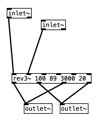
Finally we get to the reverb subroutine itself. The object that does most of the heavy lifting in this subroutine is rev~ 100 89 3000 20. This is a stereo input, four output reverb unit. Accordingly the first two inlets would be the left and right input. The other four inlets are covered by creation arguments (100 89 3000 20). These four values correspond to: output value, liveness, crossover frequency, and high frequency dampening. The output value is expressed in decibels. When expressed in this manner we can think of a change of 10 dB as doubling or halving the volume of a sound. We often consider the threshold of pain (audio so loud that it is physically painful to us) as starting around 120 dB. Thus, 100 dB, while considered to be loud, is 1/4 as loud as the threshold of pain. The liveness setting is really a feedback level (how much of the reverberated sound is fed back through the algorithm). A setting of 100 would yield reverb that would go on forever, while the setting 80 would give us short reverb. Accordingly, 89 gives us a moderate amount of reverb.

The last two values, cross over frequency and high frequency dampening work somewhat like a low pass filter. In the acoustic world low frequencies reverberate very effectively, while high frequencies tend to be absorbed by the environment. That is why a highly reverberant space like a cave or a cathedral has a dark sound to its reverb. In order to model this phenomenon, most reverb algorithms have an ability to attenuate high frequencies built into them. In this case 3,000 Hz is the frequency at which dampening begins. Here dampening is expressed as a percentage. Thus, a dampening of 0 would mean no dampening occurs, while 100 would mean that all of the frequencies about the crossover frequency are dampened. Accordingly, 20 seems like a moderate value. The outlets from pd reverb are then multiplied by the right outlet of cg-dw, applying the amount of reverb desired, and sent to the right and left outputs using throw~ outL and throw~ outR respectively.

For the EYESY I used the patch Mirror Grid Inverse – Trails. The EYESY’s five knobs are used to control: line width, line spacing, trails fade, foreground color, and background color. EYESY programming is accomplished in the language Python, and utilizes subroutines included in a library designed for creating video games called pygame.

An EYESY program is typically in four parts. The first part is where Python libraries are imported (pygame must be imported in any EYESY program). This particular program imports: os, pygame, math, and time. The second part is a setup function. This program uses the code def setup(screen, etc): pass to accomplish this. The third part is a draw function, which will be executed once for every frame of video. Accordingly, while this is where most of the magic happens, it should be written to be as lean as possible in order to run smoothly. Finally, the output should be routed to the screen.

In terms of the performance, I occasionally used knob 2 to change the pitch. I left reverb at 100%, and mix around 50% for the duration of the improvisation. I could have used the keyboard of the Organelle to play specific pitched versions of the audio input. Next month I hope to tackle additive synthesis, and perhaps use a webcam with the EYESY. Given that I’ve given a basic explanation of the first two parts of an EYESY program, in future months I hope to go through EYESY programs in greater detail.

Experiment 5: 2opFM

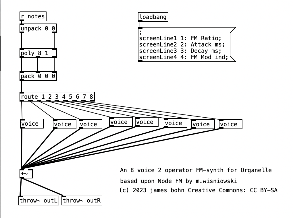
As was the case with Experiment 4, this month’s experiment has been a big step forward, even if the music may not seem to indicate an advance. This is due to the fact that this is the first significant Organelle patch that I’ve created, and that I’ve figured out how to connect the EYESY to wifi, allowing me to transfer files to and from the unit. The patch I created, 2opFM, is based upon Node FM by m.wisniowski.

As the name of the patch suggests it is a two operator FM synthesizer. For those who are unfamiliar with FM synthesis, one of the two operators is a carrier, which is an audible oscillator. The other operator is an oscillator that modulates the carrier. In its simplest form, we can think of FM synthesis as being like vibrato. One oscillator makes sound, while the other oscillator changes the pitch of the carrier. We can think of two basic controls that affect the nature of the vibrato, the speed (frequency) of the modulating oscillator, and the depth of modulation, that is how far away from the fundamental frequency does the pitch move.

What makes FM synthesis different from basic vibrato is that typically the modulating oscillator is operating at a frequency within the audio range, often at a frequency that is higher in pitch than that of the carrier. Thus, when operating at such a high frequency, the modulator doesn’t change the pitch of the carrier. Rather it functions to shape the waveform of the carrier. FM Synthesis is most often accomplished using sine waves. Accordingly, as one applies modulation we start to add harmonics, yielding more complex timbres.

Going into detail about how FM synthesis shapes waveforms is well beyond the scope of this entry. However, it is worth noting that my application of FM synthesis here is very rudimentary. The four parameters controlled by the Organelle’s knobs are: transposition level, FM Ratio, release, and FM Mod index. Transposition is in semitones, allowing the user to transpose the instrument up to two octaves in either direction (up or down). FM Ratio only allows for integer values between 1 and 32. The fact that only integers are used here means that the result harmonic spectra will all conform to the harmonic series. Release refers to how long it will take a note to go from its operating volume to 0 after a note ends. The FM Mod index is how much modulation is applied to the carrier, with a higher index resulting in more harmonics added to a given waveform. I put this parameter on the leftmost knob, so that when I control the organelle via my wind controller, a WARBL, increases in air pressure will result in richer waveforms.

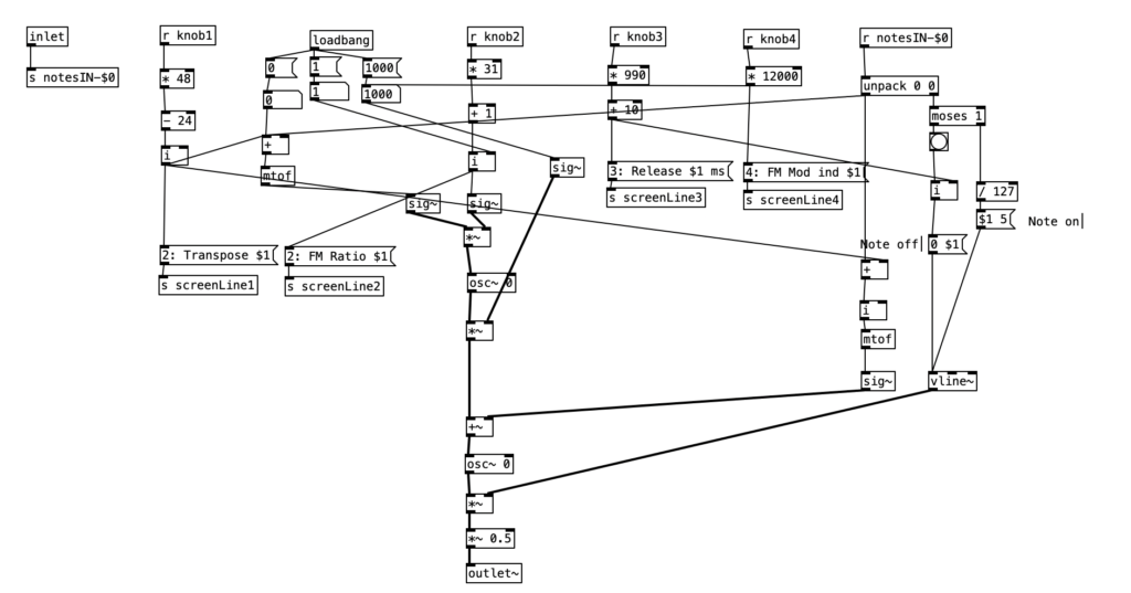
As can be seen in the screenshot of main.pd above, 2opFM is an eight voice synthesizer. Eight voice means that eight different notes can be played simultaneously when using a keyboard instrument. Each individual note is passed to the subroutine voice. Determining the frequency of the modulator involves three different parameters: the MIDI note number of the incoming pitch, the transposition level, and the FM ratio. We see the MIDI note number coming out of the left outlet of upack 0 0 on the right hand side, just below r notesIN-$0. For the carrier, we simply add this number to the transposition level, and then convert it to a frequency by using the object mtof, which stands for MIDI to frequency. This value is then, eventually passed to the carrier oscilator. For the modulator, we have to add the MIDI note number to the transposition level, convert it to a frequency, again using mtof, and multiplying this value by the FM Ratio.

In order to understand the flow of this algorithm, we first have to understand the difference between control signals and audio signals. Audio signals are exactly what they sound like. In order to have high quality sound audio signals are calculated at the sample rate, which is 44,100 samples per section by default. In Pure Data, calculations that happen at this rate are indicated by a tilde following the object name. In order to save on processor time, calculations that don’t have to happen so quickly are control signals, which are denoted by a lack of a tilde after the object name. These calculations typically happen once every 64 samples, so approximately 689 times per second.

Knowing the difference between audio signals and control signals, we can now introduce two other objects. The object sig~ converts a control signal into an audio signal. Likewise, i converts a float (decimal value) to an integer, by truncating the value towards zero, that is positive values are rounded down, while negative values are rounded up.

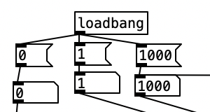
Keep in mind the loadbang portion of voice.pd is used to initialize the values. Here we see the transposition level set at zero, the FM ratio set to one, and the FM Mod index set to 1000. The values from the knobs come in as floats between 0 and 1 inclusive. Thus, typically in order to get useable values we have to perform mathematical operations to rescale them. Under knob 1, we see the transposition level multiplied by 48, and then we subtract 24 from that value. This will yield a value between -24 (two octaves down) and +24 (two octaves up). Under knob 2, we see the FM ratio multiplied by 31, and then we add one to this value, resulting in a value between 1 and 32 inclusive. Both of these values are converted to integers using i.

The scaled value of knob 1 (transposition level) is then added to the MIDI note number, and then turned into a frequency using mtof and converted to an audio signal using sig~. This is now the fundamental frequency of carrier oscillator. In order to get the frequency of the modulator, we need to multiply this value to the scaled value of knob 2. This frequency is then fed to the leftmost inlet of the modulating oscillator (osc~). The output of the modulating oscillator is then multiplied by the scaled output of knob 4 (0 to 12,000 inclusive), which is then in turn multiplied by the fundamental frequency of the carrier oscillator before being fed to the leftmost inlet of the carrier oscillator (osc~). While there is more going on in this subroutine, this explains how the core elements of FM synthesis are accomplished in this algorithm.

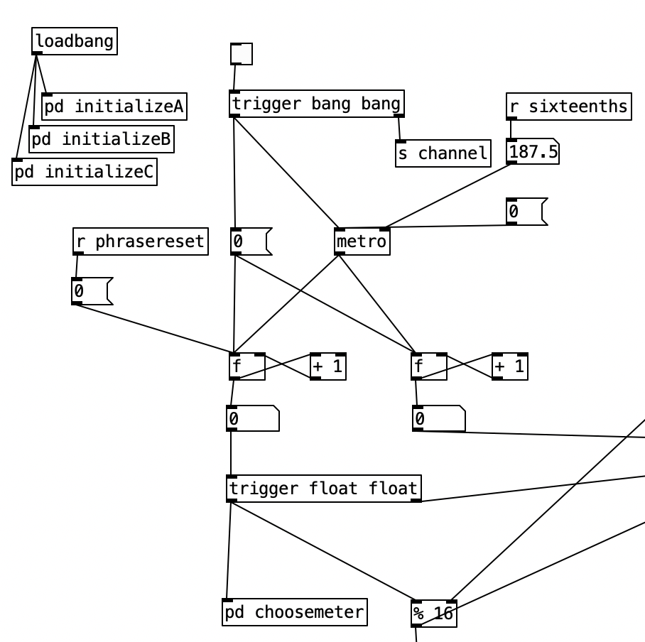
The algorithm that is used to generate the accompaniment is largely the same as the one used for Experiment 4 with a couple of changes. First, after completing Experiment 4 I realized I had to find a way to set the sixteenth note counter to zero every time the meter is changed. Otherwise, occasionally when changing from one meter to another there may be one or two extra beats. However, reseting the counter to zero ruins the subroutine that sends automation values. Thus, I had to use two counters, one that keeps counting without being reset (on the right) and one that gets reset every time the meter changes (on the left).

Initially I made a mistake by choosing the new meter at the beginning of a phrase. This caused a problem called a stack overflow. At the beginning of a phrase you’d chose a new meter, which would cause the phrase to reset, which would a new meter to be chosen, which then repeats in an endless loop. Thus, I had chose a new meter at the end of a phrase.

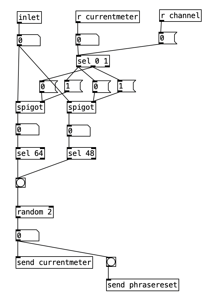
Inside pd choosemeter, we see the phrase counter being sent to two spigots. This spigots are turned on or off from depending on the value of currentmeter. The value 0 under r channel sets the meter for the first phrase to 4/4. Using the nomenclature of r channel is a bit confusing, as s channel is included in loadbang, and was simply included to initialize the MIDI channel numbers for the algorithm. In a future iteration of this program, I may retitle these values as s initializevalues and r initializevalues to make more sense.

Underneath the two spigots, we see sel 64 and sel 48, This finds the end of the phrase when we are in 4/4 (64) or 3/4 (48). Originally I had used the values 63 and 47 as these would be the numbers of the last sixteenth note of each phrase. However, when I did that I found that the algorithm skipped the last sixteenth note of the phrase. Thus, by using 64 and 48 I actually am choosing the meter at the start of a phrase, but now reseting the counter to zero no longer triggers a recursive loop. Regardless, whenever either sel statement is triggered the next meter is chosen randomly, with zero corresponding to 4/4 and 1 corresponding to 3/4. This value is then sent to other parts of the algorithm using send currentmeter, and the phrase is reset by sending a bang to send phrasereset.

As previously noted, I figured out how to connect the EYESY to wifi, allowing me to transfer files two and from the unit. Amongst other things, this allows me to download new EYESY programs from patchstorage.com and add them to my EYESY. I downloaded a patch called Image Shadow Grid, which was developed by dudethedev. This algorithm randomly grabs images stored inside a directory, adds them to the screen, and manipulates them in the process.

I was able to customize this program without changing any of the code simply by changing out the images in the directory. I added images related to a live performance of a piece from my forthcoming album (as Darth Presley). However, up to this point I’d been using the EYESY to respond mainly to audio volume. Some algorithms, such as Image Shadow Grid, use triggers to incite changes in the video output. The EYESY has several trigger modes. I chose to use the MIDI note trigger mode. However, in order to trigger the unit I now have to send MIDI notes to the EYESY.

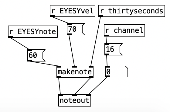
This constitute the other significant change to the algorithm that generates the accompaniment. I added a subroutine that sends notes to the EYESY. Since the pitch of the notes don’t matter, I simply send the number for middle C (60) to the unit. Otherwise the subroutine which determines whether a note should be sent to the EYESY functions just like those used to generate any rhythm, that is it selects between one of three rhythmic patterns for each of the two meters, each pattern of which is stored as an array.

As with last month, the significant weakness in this month’s experiment is my lack of practice on the WARBL. Likewise, it would have been useful if I had the opportunity to add a third meter to the algorithm that generates the accompaniment. The Organelle program 2opFM is not quite as expressive with the WARBL as it had been in experiment 2 and 4. Changes in the FM Mod Index aren’t as smooth as I had hoped they’d be. Perhaps if I were to expand the patch further, I’d want to add a third operator, and separate the FM Mod Index into two parts, one where you set the maximum level of the index, and another where you set the current level, so you can set it where the maximum breath pressure on the WARBL only yields a subtle amount of modulation.

In terms of the EYESY, I doubt I will begin writing programs for it next month, I may experiment with already existing algorithms that allow the EYESY to use a webcam. However, hopefully by October I can be hacking some Python code for the EYESY. My current plan is to experiment with some additive synthesis next month, so stay tuned.

Experiment 4: NES EWI

While this month’s experiment may not seem musically much more advanced than Experiment 2, this month has actually been a significant step forward for me. I finished reading Organelle: How to Program Patches in Pure Data by Maurizio Di Berardino. More importantly, I finally got the WiFi working on my Organelle which allows me to transfer patches back and fourth between my laptop and the Organelle. I used that feature to transfer a patch called NESWave Synth by a user called blavatsky. This patch uses waveforms from the Nintendo Entertainment System, the Commodore 64, and others as a basis for a synthesizer. However, the synthesizer allows one to mix in some granular synthesis, add delay, add a a phasor, and other fancy features.

I made one minor tweak to NESWave Synth. In experiment 2 I used my WARBL wind controller to control the filter of Analog Style, I wanted to do the same with NESWave. On Analog Style, the resonance of the filter is on knob 3 and the cutoff frequency is on knob 4. On NESWave Synth, these to settings are reversed. So, I edited NESWave Synth so resonance is on knob 3 and cutoff frequency is on knob 4. I titled this new version of the patch NES EWI. This patch me to go from controlling Analog Style to NES EWI without changing the settings on my WARBL.
As NESWave Synth / NES EWI has a lot of other features / settings. During this experiment, I setup all the parameters of the synth the way I wanted, and didn’t make any changes in the patch as I performed, although again the breath pressure of the WARBL was controlling the filter cutoff frequency. Another user noted that NESWave Synth is complicated enough to warrant patch storage, although to the best of my knowledge no one has implemented such a feature yet.

The tweak I made to NESWave Synth is insignificant enough to not warrant coverage here. Accordingly I’ll go over changes I made to the PureData algorithm that generated the accompaniment for Experiment 2. Experiment 2 uses the meter 4/4 exclusively. I’ve been wanting to build an algorithm that randomly selects a musical meter at the beginning of each phrase. While the basic mechanics of this is easy, in order to add a second meter, I have to double the number of arrays that define the musical patterns.

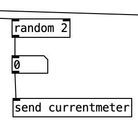
In Experiment 4 I add the possibility of 3/4. Choosing between the two meters is simple. Inside the subroutine pd instrumentchoice I added a simple bit of code that randomly chooses between 0 and 1, and then sends that value out as currentmeter.

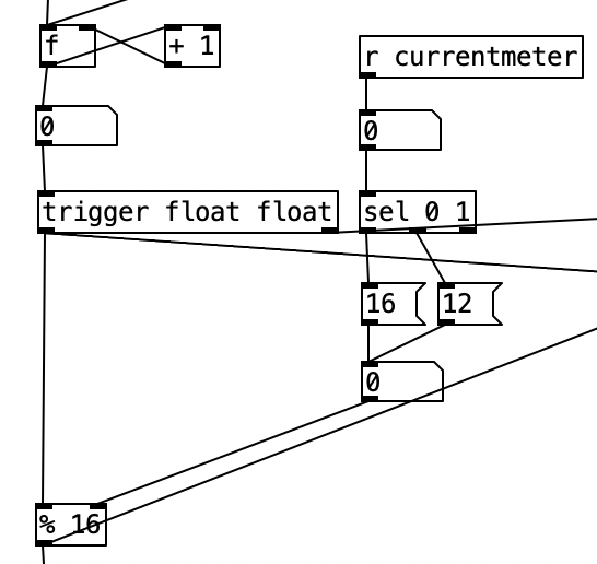
However, making this change causes three problems. The first is that the length of each measure now has change from 16 sixteenth notes to 12 sixteenth notes. That problem is solved in the main routine by adding an object that receives the value of currentmeter and uses that to select between an option that passes the number 16 or the number 12 to the right inlet of a mod operation on the global sixteenth note counter. This value will overwrite the initial value of 16 in the object % 16. As I write this, I realize I need to also reset the counter to 0 whenever I send a new meter so every phrase starts on beat 1. I can make that change in the next iteration of the algorithm.

The next problem is that I had to change the length of each phrase from 64 (4 x 16) for 4/4 to 48 (4 x 12) for 3/4. This is solved exactly the same way by passing the value of currentmeter to an object that selects either 64 or 48, and passes that value to the right inlet of a mod operation, overwriting the initial value of 64. Note that I also pass the value of currentmeter to a horizontal radio button so I can see what the current meter is. I can’t say that I actually used this in performance, but as I practice with this algorithm I should be able to get better at changing on the fly between a 4/4 feel and a 3/4 feel. Also, this should be much easier for me when I play an instrument I am more comfortable with than the EWI. I have also added a visual metronome using sel 0 4 8 12 each of which passes to a separate bang object. Doing this will cause each bang to flash on each successive beat. In future instances of this algorithm I may choose to just have it show where beat one is, as counting beats will become more complicated as I add asymetrical meters.

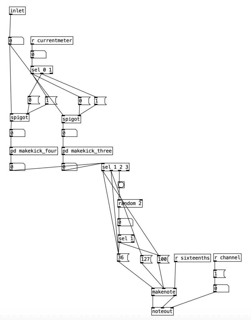
The final problem is that every subroutine that generates notes (pd makekick, pd makesnare, pd makeclap, pd makehh, pd makecymbal pd maketoms pd makecowbell pd makepizz, pd makekeys, pd makefm) needs to be able to switch between using patterns for 4/4 and patterns for 3/4. While I made these changes to all 10 subroutines, it is the same process for each, so I’ll only show one version. Let’s investigate the pd makekick subroutine. The object inlet receives the counter for the current sixteenth note, modded to 16 or 12. This value is then passed to the left inlet of two different spigot objects. In PureData spigots pass the value of the left inlet to the outlet if the value at the right inlet is greater than zero. Thus, we can take the value of currentmeter to select which spigot gets turned on, and conversely, which one gets turned off, using the 0 and 1 message boxes.

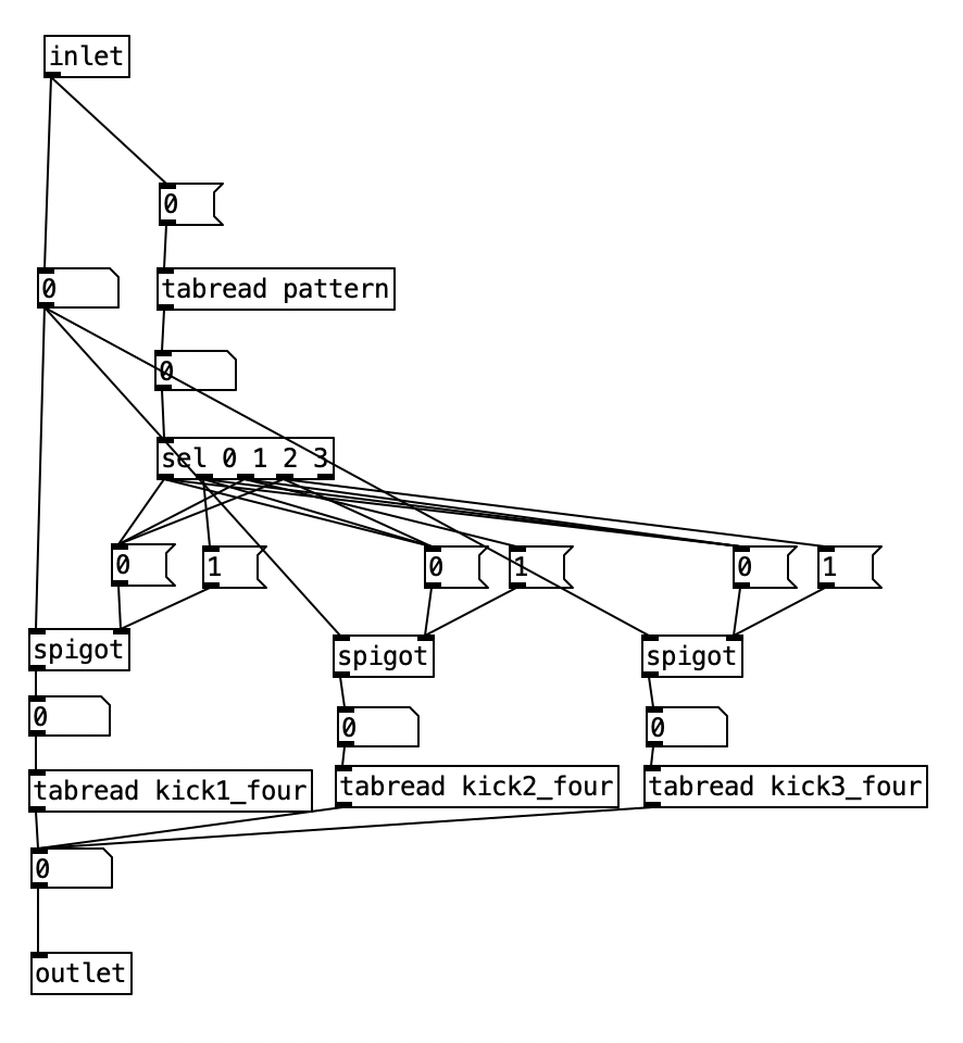
Now we know which meter is active, we will then pass to one of two subroutines which picks the current pattern. One of these subroutines pd makekick_four is for 4/4. The other, pd makekick_three is for 3/4. Both have essentially the same structure, so let’s look inside pd makekick_four. This subroutine uses the same structure as pd makekick. Again, the inlet receives the current value of the sixteenth note counter. Again, we use spigots to route this value, however, this time we use three spigots as there are three different patterns that are possible. This routing is accomplished using the current value of pattern. The 0 position of this array stores the value for kick drum patterns. Technically speaking, there are four different patterns, 0, 1, 2, 3, with the value 0 meaning that there is no active pattern, resulting in no kick drum pattern. Again, a sel statement that passes to a series of 0 and 1 message boxes turn on and off the three spigots. The object tabread objects below read from three different patterns kick1_four, kick2_four, kick3_four. The value at this point is passed back out to the pd makekick subroutine. Since the possible values, 0, 1, 2, or 3, are the same whether the pattern is in 4/4 or 3/4, these values are then passed to the rest of the subroutine, which either makes an accented note, an unaccented, note, or calculates a 50% chance of an unaccented occuring. A fourth possibility, no note, happens when the value is 0. By not including 0 in the object sel 1 2 3 we insure no note will happen in that case.

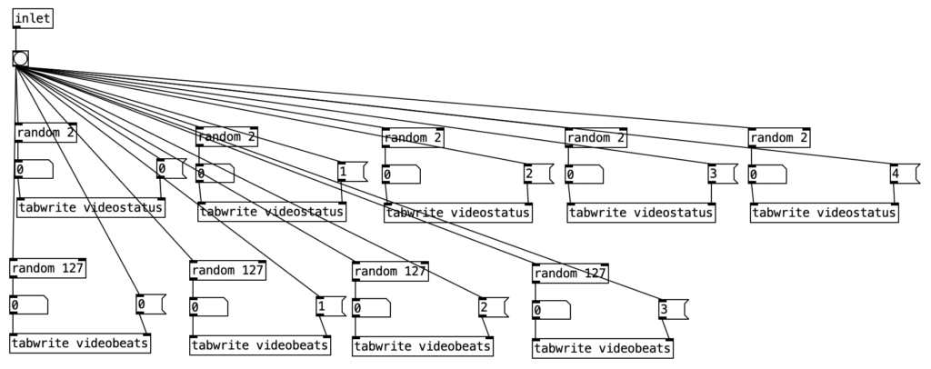
While I still haven’t looked into programming the EYESY, I did revise the PureData algorithm that controls the EYESY. In Experiment 2, all of the changes to the EYESY occur very gradually, resulting in slowly evolving imagery. In Experiment 4, I wanted to add some abrupt changes that occur on the beat. Most EYESY algorithms use knob 5 to control the background color. I figure that would be most apparent change possible, so in the subroutine pd videochoice I added code that would randomly choose four different colors (one for each potential beat), and to store them in an array called videobeats. Notice that each color is defined as a value between 0 and 126 (I realized while writing this, I could have used random 128) as we use MIDI to control the EYESY, and MIDI parameters have 128 different values.

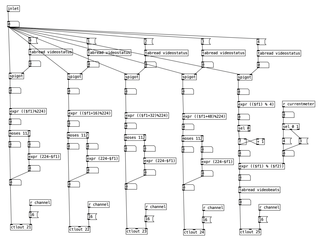
Now we have revise pd videoautomation to allow for this parameter control. The first four knobs use the same process that we used in Experiment 2. For the fifth knob, the 4 position in the array videostatus, we first check to see whether changes should happen for that parameter by passing the output of tabread videostatus to a spigot. When tabread videostatus returns a one, the spigot will turn on, otherwise, it will shut down. When the spigot is open, the current value of sixteenth note counter is passed to an object that mods the by 4. When this value is 0, we are on a beat. We then have a counter that keeps track of what the current beat number is. We then however, have to mod that either 4 for 4/4 or 3 for 3/4. The is accomplished using expr (($f1) % ($f2)). Here we pass the current meter to the right inlet, corresponding to $f2. We do thus using the value of currentmeter to select between a 4 and 3 message box. We can then get the color corresponding to the beat by returning the value of videobeats, and send that out to the EYESY using ctrlout 25 (25 being the controller number for the fifth knob of the EYESY).

In terms of the video, it is clear that I really need to practice my EVI fingerings. I am considering forcing the issue by booking a gig on the instrument to force me to practice more. I find that the filter control on Analog Style felt more expressive to me than the control on NES EWI. Though perhaps I need to recalibrate the breath control on the WARBL. I hope to do a more substantial hack next month, perhaps creating a two operator FM instrument. I also hope to connect the EYESY to WiFi so I can add more programs to it.

Experiment 3: Deterior

June has been busy for me. I’m behind where I wanted to be at this point in my research. This is due in part to not having a USB WiFi adapter to transfer files onto the Organelle and the EYESY. Accordingly, this month’s post will be light on programming, focusing on the Pure Data object route. I’ll be ordering one later this week, and will hopefully be able to take a significant step forward in July.
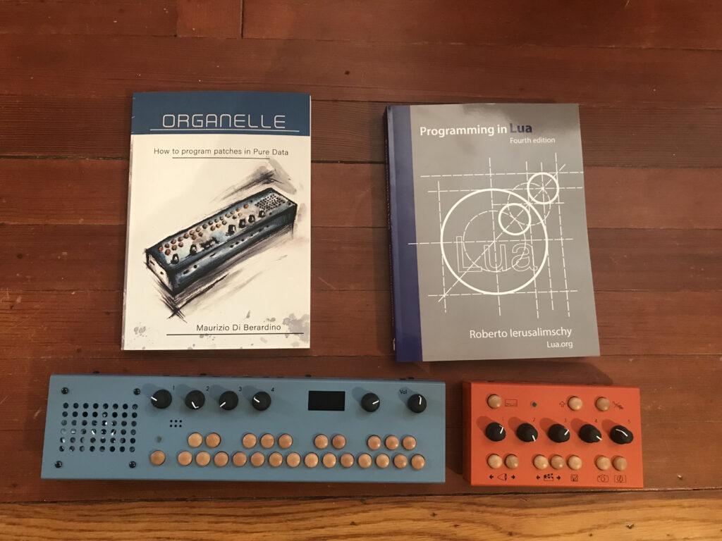
Accordingly, my third experiment in my project funded by Digital Innovation Lab at Stonehill College investigates the use of the preset patch Deterior (designed by Critter and Guitari). Deterior is an audio looper combined with audio effects in a feedback loop. In this experiment I run audio from a lap steel guitar.

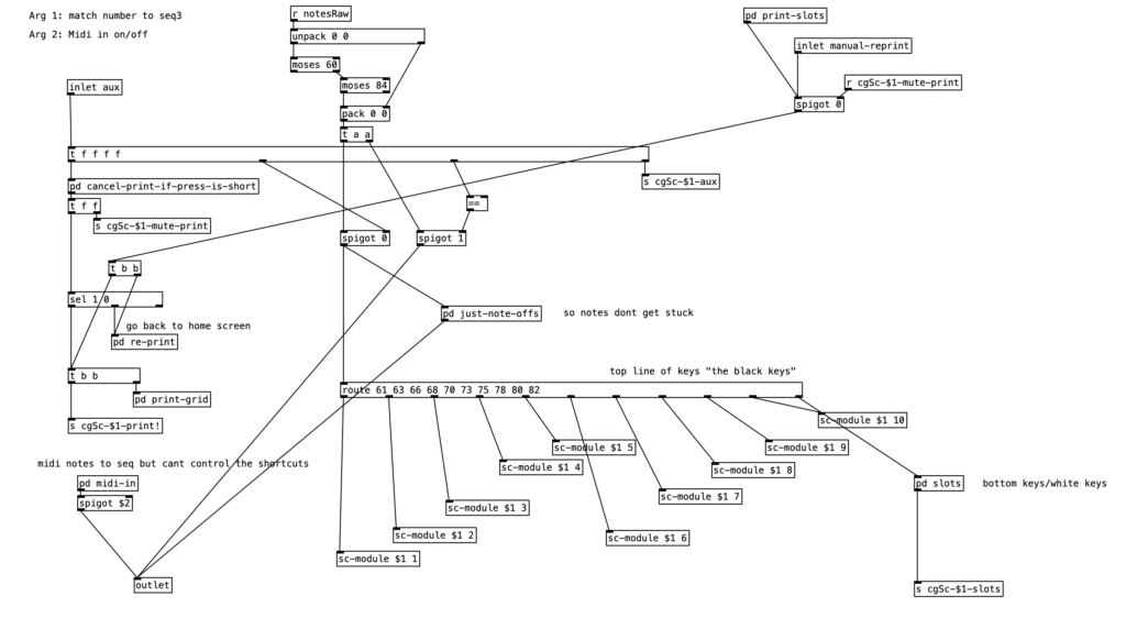
The auxiliary key is used in conjunction with the black keys of the keyboard to select various functions. The lowest C# toggles loop recording on or off , the next D# stores the recording, the F# reverts to the most recent recording (removing any effects), the G# empties the loop, while A# toggles the input monitor. The upper five black keys of the instrument toggle on or off the five different effects that are available: noise (C#), clip (D#), silence (F#), pitch shift (G#), and filter (A#). The parameters of these effects cannot be changed from the Organelle, they can only be turned on or off. The routing of these auxiliary keys is accomplished through the subroutine shortcut.pd, using the statement route 61 63 66 68 70 73 75 78 80 82. Note that these numbers correspond to the MIDI note numbers for the black keys from C#4 to A#5.

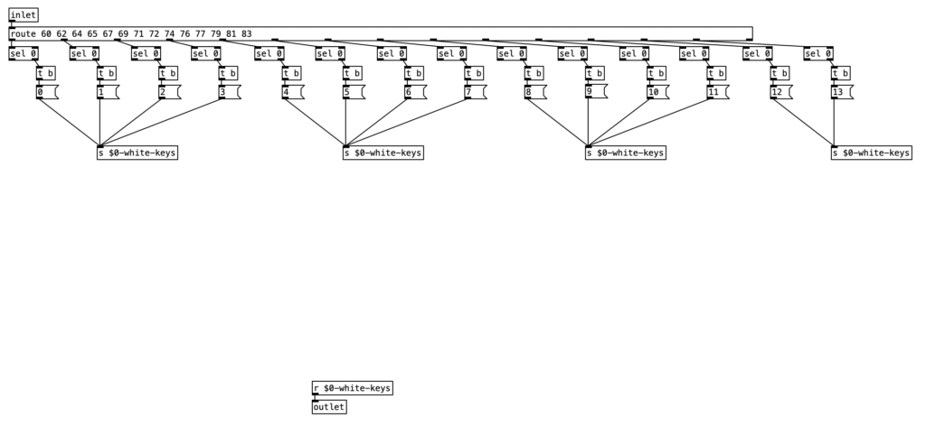
A similar technique is used with the white keys of the instrument. These keys are used as storage slots for recorded loops, which can be recalled at any time once they are stored. This is initiated in pd slots, using route 60 62 64 65 67 69 71 72 74 76 77 79 81 83. These numbers correspond to the white keys from C4 to B5.

In this experiment I start using only filtering. Eventually I added silence, clipping, noise, and finally pitch shifting. Specifically, you can hear noise entering at 5:09. After adding all the effects in I stopped playing new audio, and instead focused on performing the knobs of the Organelle. Near the end of the experiment I start looping and layering a chord progression: Am, Dm, C#m, to Bm. When I introduce this progression I add one chord from this progression at a time.

In terms of the EYESY, I ran the recording through it so I would have my hands free to perform the settings. Again, I used a preset as I did not have a wireless USB connection to transfer files between my laptop and the EYESY. Hopefully next month I should be able to do deeper work with the EYESY.

Like Experiment 1, I had a lot of 60 cycle hum in the recording, which I tried to minimize by turning down the volume on the lap steel when I’m not recording sound. That process created it’s own distracting aspect of having the 60 cycle hum fade in and out in a repeating loop.

Experiment 2: Analog Style


May has been a busy month for me. Thus, my second experiment in my project funded by Digital Innovation Lab at Stonehill College investigates the use of the preset patch Analog Style (designed by Critter and Guitari). To be specific, I am using a WARBL wind controller with EVI fingering to control the patch. I am using the breath control on the WARBL to control the cutoff frequency of Analog Style (using MIDI controller 24).

Due to the busyness of the end of the semester, this experiment features no original programming on the organelle. However, I did create a program in Pure Data to create accompaniment and drive the EYESY. To accompany the experiment, I used the H.E.A.P, the Housatonic Electronic Algorithmic Philharmonic. This a fun, frivolous name I’ve given to a small, battery powered synthesizer / sampler setup I’ve assembled for live performance. It consists of three synthesizers / samplers: a Volca Sample 2 (which provides 10 channels of late 1980s style lo fidelity digital sampling), a Volca Keys (which can be used as an analog monophonic or 3 note polyphonic synthesizer), and a Volca FM 2 (which is a clone of the 1980s classic, the Yamaha DX7, the best selling synthesizer of all time). I’ve also begun to think of the EYESY, as we’ll see later, as part of the H.E.A.P.

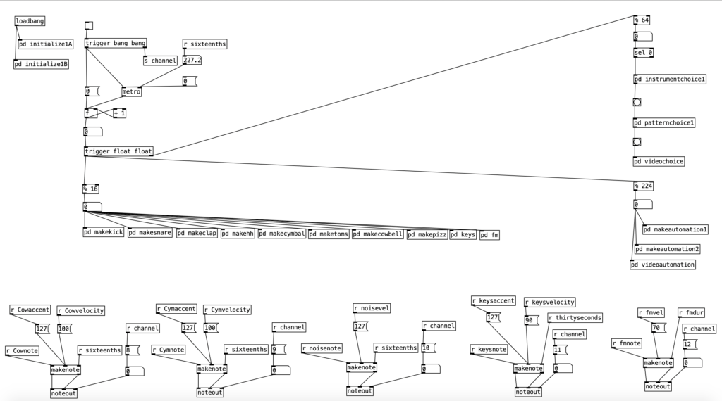
I won’t go into great detail about the program that generates the accompaniment for Experiment 2, as I have other blog posts that go into detail about various algorithms included in the program. Ultimately, the program is intended to generate relatively generic, but fairly usable R&B esque slow jams. The music is in common time using sixteenth notes. The portion of the program including and beneath % 16 (mod 16) ensures that the resulting music will have 16 pulses per measure. Likewise, the instrumentation and musical patterns change every four measures. This is enabled by the part of the program including and beneath % 64 (four measures of sixteenth notes adds up to 64).

The Volca Sample is being used to provide the drum beat, and some string pizzicato (see pd makepizz). The Volca Keys provides some synthesized bass patterns that run two measure loops. The Volca FM provides four chord, four note chord progressions that repeat every two measures. To create these chord progressions I used some music programming techniques that I’ve covered in a previous blog entry, though in this experiment I am use the brass friendly key of G minor.

One of the newer programming tricks I used in this program is an algorithm designed to drive the EYESY. While the EYESY generates hypnotic, interactive video animations, left to its own devices it can get a bit repetitive fairly quickly. In order to generate anything that seems even remotely dynamic some one needs to perform the EYESY by rotating its five knobs. This is an impossibility for any performing musician, save for a vocalist. Thankfully, we can do the equivalent of turning the knobs on the EYESY through MIDI using controllers 21 through 25.

The algorithm I’ve created to drive the EYESY is designed to make slow, evolving changes. To control these changes I’ve created a table called videostatus. It consists of five positions that contain a one or a zero to denote whether changes should be make or not made to a given knob during the current four measure phrase.

The subroutine pd videochoice is triggered at the beginning of every four measure phrase. It generates five different random numbers that are either a zero or a one. These results are then stored in the table videostatus.

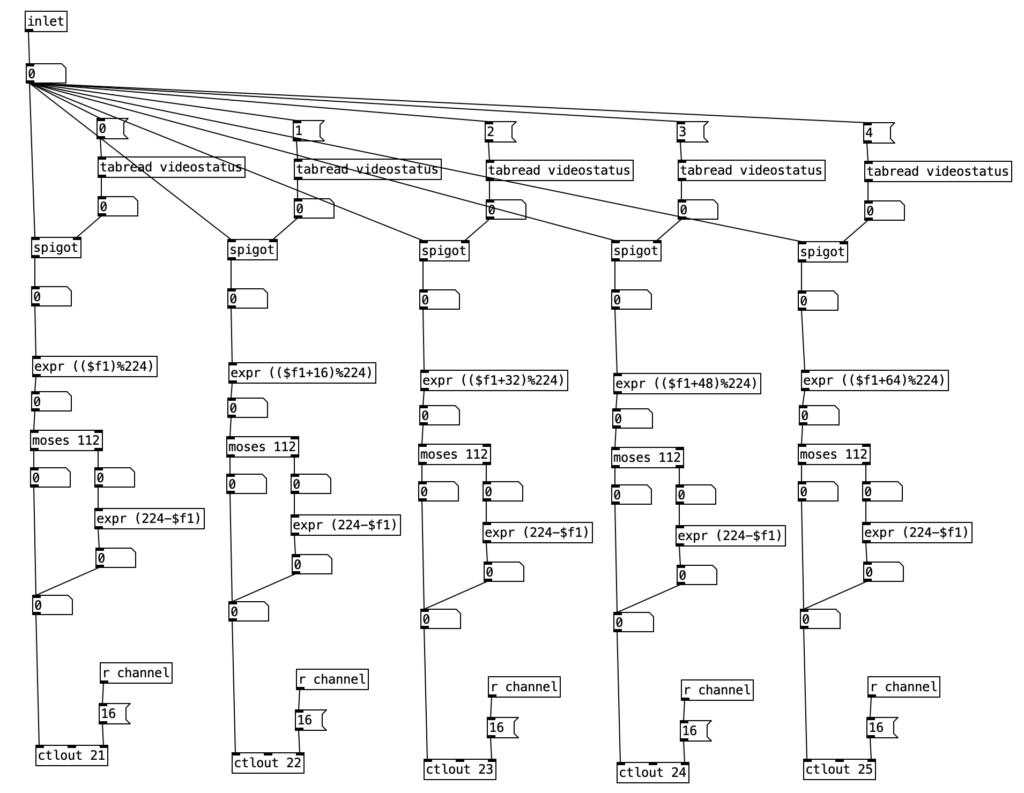
The subroutine pd videoautomation updates the knob positions on the EYESY once every sixteenth note. It is passed the current sixteenth note number modded by the number 224, which corresponds to 14 measures of sixteenth notes. The subroutine contains five nearly identical columns, each of which corresponds to each of the five knobs on the EYESY. First the algorithm checks the current states of each of the five positions of videostatus table. When that value is one, that allows the current sixteenth note number to pass through the spigot. This value is passed through an expr statement that displaces the sixteenth note number. The column corresponding to knob one is not displaced, but each subsequent column is displaced by one measure (16 sixteenths), which is then modded to stay between 0 and 224. The statement moses 112 is used to determine whether we should be counting up to 112, or counting down to 0. This is accomplished by having numbers that are greater than 112 to pass through expr (224-$f1), which causes the result to get small as the input value is increased. The result of this is then passed to one of the five controller values (21-25) on MIDI channel 16 (the channel I’ve set my EYESY to).

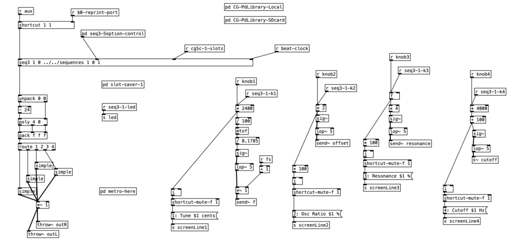
Since I went over the mother patch in the previous experiment, I’ll start with going over main.pd for the Analog Style patch. We can see that knob one controls the tuning of the patch, while knob two creates an offset frequency for a second oscillator. The third knob sets the resonance of the low pass filter, while the fourth knob (the one I am controlling using the WARBL) sets the cutoff frequency of filter. To learn more about what low pass filters are, check out my blog entry on Low Pass Filters in LogicPro. However, to summarize briefly in relationship to the WARBL, when the amount of breath coming through is low, that in turn sets the cutoff frequency to be low as well, resulting in less sound (and only low frequency sound) to come out of the Organelle.

We can also see that this patch allows for sequencing when the aux button is down. However we will not go through how sequencing works today. We will however go into simple, which is the subroutine that creates the sound. We can see two oscillators, blsaw, in this subroutine that generate sawtooth waves. For more information on subtractive synthesis waveforms (including sawtooth waves), check out my blog entry on Subtractive Synthesis Waveforms in Logic Pro. One of those two blsaw oscillators is modified by the offset of knob two. The mixture of these two oscillators is passed to a low pass filter, moog~. This object also receives a center frequency to its center inlet, and a resonance value to its right most inlet. The outlet of this object is then attenuated slightly, *~ .75, before being sent to the subroutine’s outlet.

Again, I’ve found that the accompaniment generated by experiment.pd to be generic, but also fairly usable. It should be relatively easy to change the tempo, phrase length, or any number of musical patterns to create music that is stylistically different. Also, I enjoy slow evolving nature of EYESY generated video. I feel that turning on and off changes to various combinations of the five knobs add a degree of subtlety that aid in the dynamic nature of the video.

I am disappointed in my performance on the WARBL. I am still getting used to the EVI fingering on the instrument, so there are some very sour notes from time to time. However, I am very pleased with the range of the WARBL, as well as the subtle breath control the instrument provides. The fingering makes jumping octaves and fifths very easy. In future experiments I hope to get into hacking existing Organelle patches. I also plan to come up with variants of the videoautomation algorithm to create more sudden, less subtle changes to the EYESY’s settings.

Experiment 1: Granular Freezer

The first experiment in my project funded by Digital Innovation Lab at Stonehill College investigates the use of the preset patch Granular Freezer (designed by Critter and Guitari) to process audio . In this case the audio is coming from a lap steel guitar. In that I’m just getting used to both the Organelle and the EYESY, I will simply be improvising using a preset with the EYESY.

While describing his concept of stochastic music, composer Iannis Xenakis essentially also described the idea of granular synthesis in his book Formalized Music: Thought and Mathematics in Music . . .

“Other paths also led to the same stochastic crossroads . . . natural events such as the collision of hail or rain with hard surfaces, or the song of cicadas in a summer field. These sonic events are made out of thousands of isolated sounds; this multitude of sounds, seen as a totality, is a new sonic event. . . . Everyone has observed the sonic phenomena of a political crowd of dozens or hundreds of thousands of people. The human river shouts a slogan in a uniform rhythm. Then another slogan springs from the head of the demonstration; it spreads towards the tail, replacing the first. A wave of transition thus passes from the head to the tail. The clamor fills the city, and the inhibiting force of voice and rhythm reaches a climax. It is an event of great power and beauty in its ferocity. Then the impact between the demonstrators and the enemy occurs. The perfect rhythm of the last slogan breaks up in a huge cluster of chaotic shorts, which also spreads to the tail. Imagine, in addition, the reports of dozens of machine guns and the whistle of bullets adding their punctuations to this total disorder. The crowd is then rapidly dispersed, and after sonic and visual hell follows a detonating clam, full of despair, dust, and death.”

This passage by Xenakis goes into dark territory very quickly, but it is a scenario that harkened back to the composer’s past when he lost an eye during a conflict with occupying British tanks during the Greek Civil War.

Granular synthesis was theorized before it was possible. Its complexity requires computer technology that at the time it was theorized was not yet powerful enough. Granular synthesis takes an audio waveform, sample, or audio stream and chops it into grains and then resynthesizes the sound by combining them into clouds. The synthesist can often control aspects such as grain length, grain playback speed, cloud density, as well as others. Since the user can control playback speed of grains independently of the speed to which a sound travels through a group of grains, granular synthesis allows one to stretch or compress the timing of sound without affecting pitch, as well as being able to change the pitch of a sound without affecting the duration of a sound.

Granular Freezer is sort of a budget version of Mutable Instruments Clouds. I call it a budget version, as Clouds allows for the control of more than a half dozen parameters of the sound, while Granular Freezer gives the user control of four parameters, namely grain size, spread, cloud density, and wet / dry mix. These four parameters correspond to the four prominent knobs on the Organelle. Spread can be thought of as a window, that kind of functions like a delay time. In other words it is a window of past audio that the algorithm draws from to create grains. As you turn the spread down the sound starts to sound like an eccentric slap (short) delay. Wet / dry mix is a very standard parameter in audio processing. It is the ratio of processed sound to original sound that is sent to the output. The Aux button can be used to freeze the sound, that is hold the current spread in memory until the sound is unfroze. You may also use a pedal to trigger this function. One feature of the algorithm that I didn’t use was using the MIDI keyboard to transpose the audio.

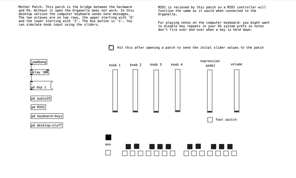
Since this is my first experiment with the Organelle, I’m not going to go through the algorithm in great detail, but I will give it an overview. All patches for the Organelle use a patch called a mother patch. The mother patch should never be altered. This controls input to and output from the Organelle. Such values are passed to and from the mother patch in order to avoid input and output errors. You can download the mother patch so you can develop instruments on a computer without having access to an Organelle. This is also a good way to check for coding errors before you upload a patch to your Organelle.

If we double click on the subroutine pd MIDI, we can see, amongst other things how the Organelle translates incoming MIDI controller data (controller numbers 21, 22, 23, & 24) to knob data . .

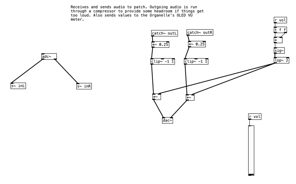
When we double click on pd audioIO, we can see how the mother patch handles incoming audio (left) as well as outgoing audio (right) . . .

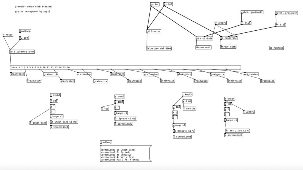
Any given Organelle patch typically consists of a main program (by convention, named main.pd), as well as a number of self contained subpatches called abstractions. In the case of Granular Freezer, in addition to the main program there are three abstrations: latch-notes.pd, grain.pd, and grainvoice.pd. Given the complexity of the program, I will only go over main.pd.

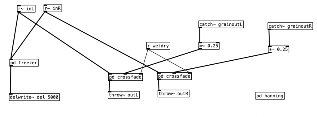
In the upper right hand quadrant we see the portion of the algorithm that handles input and output. It also controls the ability to freeze the audio (pd freezer). The objects catch~ grainoutL and catch~ grainoutR receive the granularly processed audio from grainvoice.pd. The object r wetdry receives data from knob 4, allowing the user to control the ratio of unprocessed sound to processed sound.

The lower half of main.pd sets the numerical range for each of the four knobs, sends the data to wherever it is needed (as was done with wetdry), and sets & sends the text to be displayed on the Organelle’s screen. This last item causes the function of each knob to be displayed along with its current status. In the message box at the bottom of the screen, we see a similar item related to the aux key screenLine5. The part of the program that updates the display for screenLine5 is in pd freezer.

In the improvisation I run a six string lap steel using C6 tuning through a volume pedal, and then into the Organelle. I also use a foot switch to trigger the freeze function on the patch. Musically, I spend the bulk of the time improvising over an E pedal provided by an eBow on the open low E string. A lot of the improvisation is devoted to arpeggiating Am, C#m, and Em chords on the upper three strings of the instrument. During the beginning of the improvisation the mix is at 80% (only 20% of the original sound). I quickly move to 100% mix. Near the end I move to sliding pitches with the eBow. During this portion of the improvisation I experiment with the spread, and there’s a portion where I move the spread close to its minimal amount, which yields that eccentric slap delay sound (starts around 8:28). As I move the spread towards its upper end, I can use it as a harmonizer, as the spread holds the previous pitch in its memory as I move onto a new harmonizing pitch. At the end (around 9:15) I move the grain size down to the bottom (1 millisecond), and then turn the cloud density down to the bottom to function as a fade out.

With the EYESY I simply improvised the video using the audio of the video recording I made. With the mode I was using the first two knobs seemed to control the horizontal and vertical configuration of the polygons. These controls allow you to position them in rows, or in a diamond lattice configuration. You can even use these controls to get the polygons to superimpose to an extent. The middle knob seems to increase the size of the polygons, making them overlap a considerable amount. The two knobs on the right control the colors for the polygons and the background respectively. I used these to start from a green on black configuration in honor of the Apple IIe computer.

The video below will allow you to watch the EYESY improvisation and the musical improvisation simultaneously . . .

As I mentioned earlier, I consider Granular Freezer to be a budget version of Clouds. I have the CalSynth clone of Clones, Monsoon, in a synthesizer rack I’m assembling. It is a wonderful, expressive instrument that creates wonderful sounds. While Granular Freezer is a more limited instrument, it is still capable of creating some wonderful sounds. There are already a couple variants of Granular Freezer posted on PatchStorage. As I get more familiar with programming for the Organelle, I should be able to create a version of the patch that allows for far greater control of parameters.

All in all, I feel this was a successful experiment. I should be able to reuse the audio for other musical projects. However, there was some room for improvement. There was a little bit of 60 cycle hum that was coming through the system. This was likely due to a cheap pickup in my lap steel. Likewise, it would be nice if I cleaned up my studio so it would make for a less cluttered YouTube video. As I mentioned earlier it would be good to add more parameters to the Granular Freezer patch. I used Zoom to capture the video created by the EYESY, and it added my name to the lower left hand corner of the screen. Next time I may try using QuickTime for video capture to avoid that issue. By the end of the summer I hope to develop some PureData algorithms to control the EYESY to perform the video in an automated fashion. See you all back here next month for the next installment.